 EEWORLD Follow me 第2期
# 前言
虽然专业有很多课程都是跟嵌入式相关的,但当时的我一心觉得未来一定是个软件工程师,而课程中的硬件基础,我嗤之以鼻,感觉都是几十年前的老古董,根本没听。近来发现,单纯的软件已经无法满足我对计算机科学的探索,我逐渐对硬件产生兴趣,一次偶然的机会得知「Follow me 第 2 期!与得捷电子一起解锁开发板超能力! (opens new window)」活动,基于能白嫖和借此入门嵌入式,参加了这个活动。
用到的开发板为: Adafruit ESP32-S3 TFT Feather (opens new window)
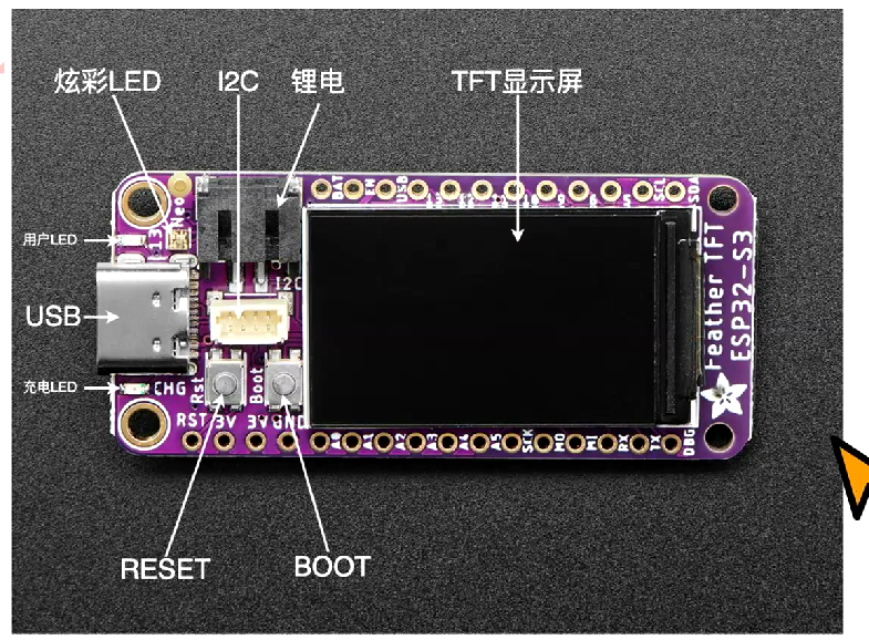
# 当前模式
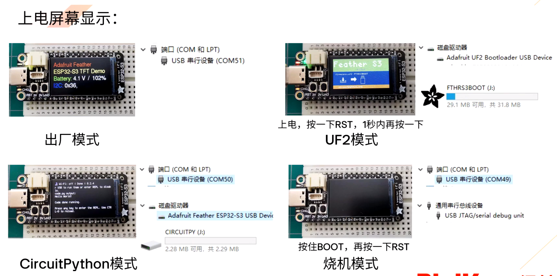
正常情况下,将开发板通过 typec 连接电脑,根据屏幕的显示就能判断出当前的显示模式是什么,如屏幕没有画面时,则电脑显示的串口信息和磁盘信息对照上图来确认。
如果开发板是全新的,上电显示的应该是出厂模式。
# 安装 CircuitPython 固件
# 下载 CircuitPython
Feather ESP32-S3 TFT Download (opens new window)
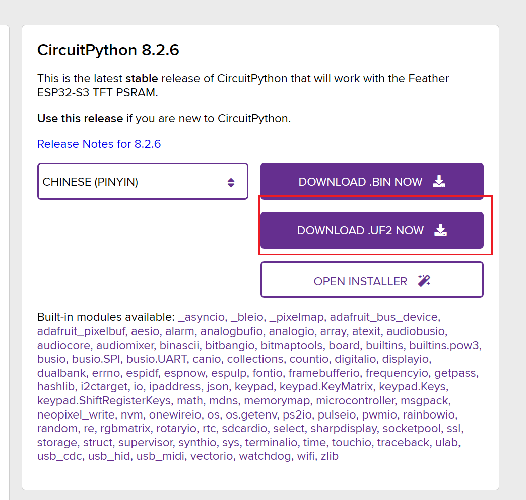
这个开发板支持 UF2,下载 UF2。
笔记
推荐下载 English 的,拼音看得比英文还难受。
# 刷入 CircuitPython
开发板连接电脑,出厂模式下,双击
RST键进入 UF2 模式把下载的
adafruit-circuitpython-adafruit_feather_esp32s3_tft-en_US-8.2.6.uf2放入开发板磁盘FTHRS3BOOT根目录即可。文件拉进去后,开发板会自动重启,进入 CircuitPython 模式。
# 开发环境
VS Code + CircuitPython 插件
- 安装 CircuitPython 插件
- VScode 打开文件夹,选择开发板在 CircuitPython 模式的磁盘根目录
- 点击 VScode 右下角,插头图标,选择串口,选择 ESP32 的
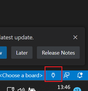
此时即可操作开发板
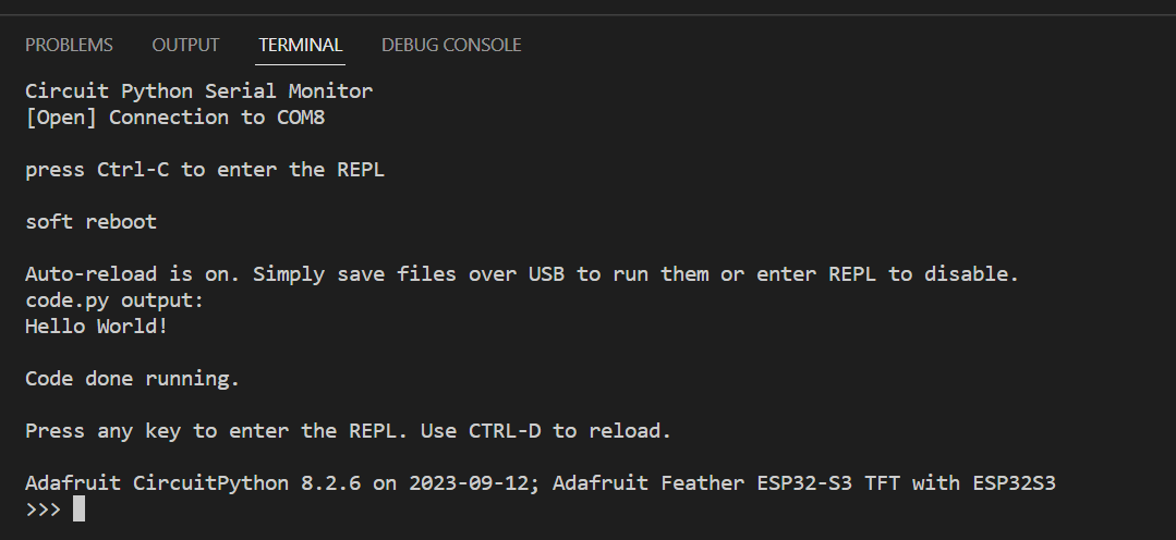
基本操作
Ctrl+C :在任意情况下输入,中断当前运行的程序
Ctrl+D :在空行的情况下输入,软重启开发板环境
Ctrl+E :在空行的情况下输入,进入粘贴模式,粘贴后 Ctrl+D 运行
PS: Ctrl+E 会与 Vscode 快捷键冲突,因此需要修改 !terminalFocus

Ctrl + Shift + P- 搜索
CircuitPython: Show Available Libraries选中

# 示例
执行代码:
- 代码编写在
code.py中,Ctrl+D软重启即可执行。 Ctrl+E进入粘贴模式,粘贴代码,然后Ctrl+D执行
# 打印开发板信息
点击查看
# 基础模块
import board
dir(board)
print("开发板名称:", board.board_id)

# 引脚定义
import re

attrs = [i for i in dir(board) if not re.match(r'^[A-Z]', i)]
GPIOS = [i for i in dir(board) if re.match(r'^[A-Z]', i)]
gpio_used = []

print("数字引脚:", end="")
for i in GPIOS:
    if re.match(r'^D\d+', i):
        print(i, end=" ")
        gpio_used.append(i)
print("")

print("模拟引脚:", end="")
for i in GPIOS:
    if re.match(r'^A\d+', i):
        print(i, end=" ")
        gpio_used.append(i)
print("")

print("TFT:", end="")
for i in GPIOS:
    if re.match(r'^TFT|DISPLAY', i):
        print(i, end=" ")
        gpio_used.append(i)
print("")

print("串口:", end="")
for i in GPIOS:
    if re.match(r'^(TX|RX|UART)$', i):
        print(i, end=" ")
        gpio_used.append(i)
print("")

print("炫彩灯珠:", end="")
for i in GPIOS:
    if re.match(r'^NEOPIXEL', i):
        print(i, end=" ")
        gpio_used.append(i)
print("")

print("SPI:", end="")
for i in GPIOS:
    if re.match(r'^(MOSI|MISO|SCK|SPI)', i):
        print(i, end=" ")
        gpio_used.append(i)
print("")

print("I2C:", end="")
for i in GPIOS:
    if re.match(r'.*(SCL|SDA|I2C)', i):
        print(i, end=" ")
        gpio_used.append(i)
print("")

print("按键:", end="")
for i in GPIOS:
    if re.match(r'^(BUTTON|BOOT0)', i):
        print(i, end=" ")
        gpio_used.append(i)
print("")

print("LED:", end="")
for i in GPIOS:
    if re.match(r'(LED|L)', i):
        print(i, end=" ")
        gpio_used.append(i)
print("")

gpio_unused = [i for i in GPIOS if i not in gpio_used]
if len(gpio_unused):
    print("未分类属性:", gpio_unused)
if len(attrs):
    print("其他属性", attrs)
# 点灯
效果:循环亮 0.5 秒、暗 0.5 秒
# 基础模块,用于实现延迟
import time
# 开发板定义模块
import board
# 数字IO模块
import digitalio

# 初始化LED,board.LED 于 board.L等同
led = digitalio.DigitalInOut(board.LED)
# 设置为输出
led.direction = digitalio.Direction.OUTPUT
#led.switch_to_output()

while True:
    # 点亮LED,阻塞0.5秒
    led.value = True
    time.sleep(0.5)
    # 熄灭LED,阻塞0.5秒
    led.value = False
    time.sleep(0.5)
# 按键
效果:按下按钮,LED 灯亮起,屏幕打印 Button down ,松开按钮,LED 灯熄灭。
import board
import digitalio

# LED对象
# led.value:当前电平,亮-高-True,灭-低-False
led = digitalio.DigitalInOut(board.LED)
led.direction = digitalio.Direction.OUTPUT

# 按键对象
# board.BUTTON 与 board.BOOT0 等同
button = digitalio.DigitalInOut(board.BUTTON)
# 设置为输入,上拉,即button.value默认为不按-高-True,按下-低-False
button.switch_to_input(pull=digitalio.Pull.UP)

# 普通按键
isDown = False
while True:
    buttonIsDown = not button.value
    # 按键下与LED同步
    led.value = buttonIsDown
    if buttonIsDown and not isDown:
        # 按下 且为 第一次检测到按下
        isDown = True
        print("Button down")
    elif not buttonIsDown and isDown:
        # 松开 且为 第一次检测到松开
        isDown = False
笔记
button.switch_to_input(pull=digitalio.Pull.UP) 很绕,没按的时候是 True,按下的时候是 False,这还不能改成 Down,改了后会按键不会变 True,为了可读性,使用了一个变量 buttonIsDown 处理。
# WIFI 联网
在根目录的 settings.toml 添加以下 WIFI 信息配置
CIRCUITPY_WIFI_SSID = "your-wifi-ssid"
CIRCUITPY_WIFI_PASSWORD = "your-wifi-password"
import os
import ssl

import adafruit_requests  # 需要安装扩展
import socketpool
import wifi

TEXT_URL = "http://wifitest.adafruit.com/testwifi/index.html"
# TEXT_URL = "https://honestqiao.gitee.io/web_esptool/"

print("ESP32-S3 网络功能测试")
print("开发板MAC地址:", [hex(i) for i in wifi.radio.mac_address])

# 连接WiFi
wifi.radio.connect(os.getenv("CIRCUITPY_WIFI_SSID"), os.getenv("CIRCUITPY_WIFI_PASSWORD"))

print("开发板已连接到WiFi")
print("开发板IP地址", wifi.radio.ipv4_address)

pool = socketpool.SocketPool(wifi.radio)
requests = adafruit_requests.Session(pool, ssl.create_default_context())

print("网络请求网址", TEXT_URL)
response = requests.get(TEXT_URL)
print("请求返回内容")
print("-" * 40)
print(response.text)
print("-" * 40)

print("测试完成")
# 炫彩灯珠
import time
import board
import neopixel # 需要安装扩展
import digitalio
from rainbowio import colorwheel

# WS2812B 电源控制
power = digitalio.DigitalInOut(board.NEOPIXEL_POWER)
power.direction = digitalio.Direction.OUTPUT
power.value = True

# WS2812B设置
pixel = neopixel.NeoPixel(board.NEOPIXEL, 1)
# 亮度
pixel.brightness = 0.5

# 颜色变换
def rainbow(delay):
    for color_value in range(255):
        pixel[0] = colorwheel(color_value)
        time.sleep(delay)

while True:
    rainbow(0.02)
# 通信方式
# 总线通信 - I2C
笔记
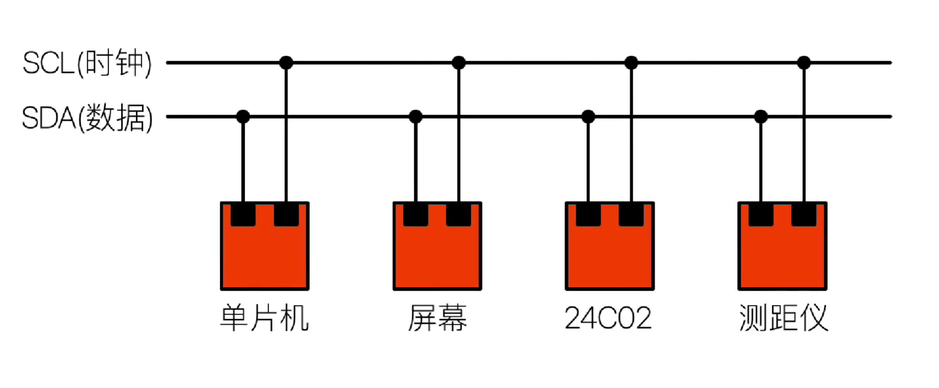
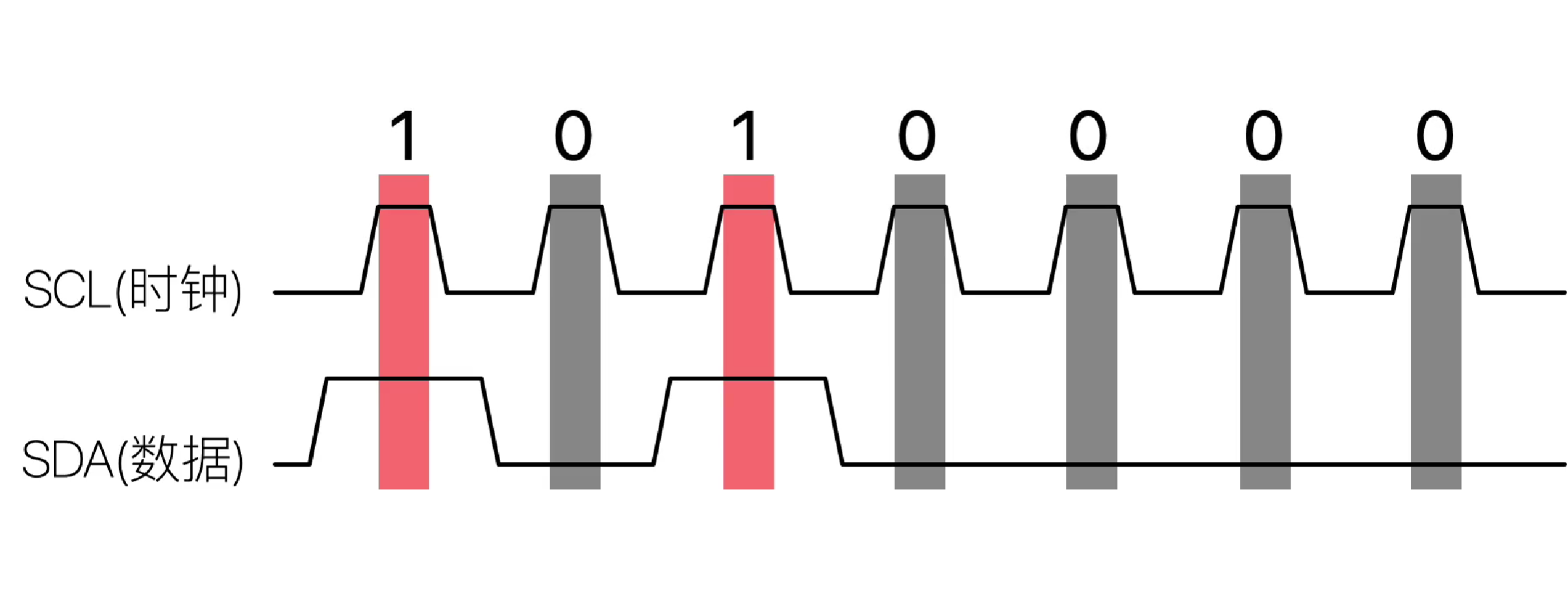
I2C 只使用两条双向漏极开路(Open Drain)线,其中一条线为传输数据的串行资料线(SDA, Serial DAta line),另一条线是启动或停止传输以及发送时钟序列的串行主频(SCL, Serial CLock line)线,这两条线上都有上拉电阻。I²C 允许相当大的工作电压范围,但典型的电压准位为 + 3.3V 或 + 5v。
参考:
# 总线通信 - SPI
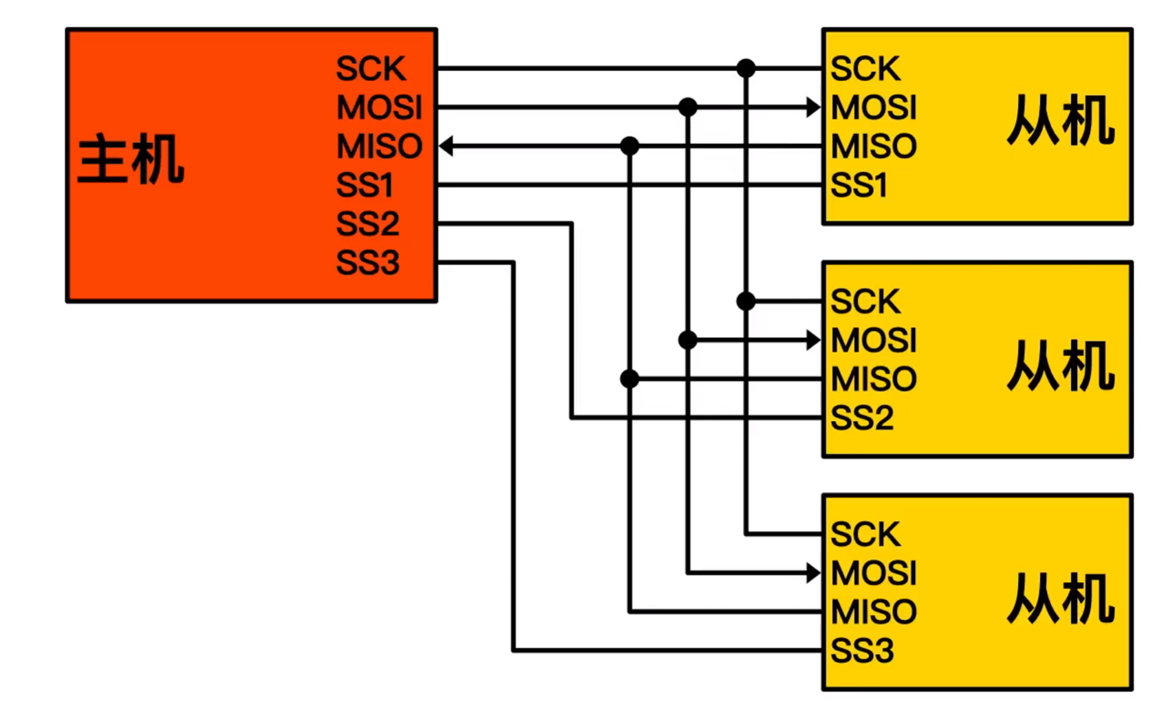
- SCLK(Serial Clock):串列时脉,由主机发出
- MOSI(Master Output, Slave Input):主机输出从机输入信号(数据由主机发出)
- MISO(Master Input, Slave Output):主机输入从机输出信号(数据由从机发出)
- SS(Slave Select):片选信号,由主机发出,一般是低电位有效
参考:
- 深入理解 SPi 通讯协议,5 分钟看懂!_哔哩哔哩_bilibili (opens new window)
- 串行外设接口(SPI) - 维基百科,自由的百科全书 (opens new window)
# 任务
# 任务 1:控制屏幕显示中文(必做任务)
任务要求:完成屏幕的控制,并且能显示中文
搭配器件:Adafruit ESP32-S3 TFT Feather
任务说明:这个任务可分为两点,一是如何在屏幕显示文本,二是在如何在屏幕显示中文文本。这个任务的难度并不大,跟着官方教程的步骤做就可以了。
主要的工作量还是在制作字体上:
下载 FontForge:https://fontforge.org/en-US/downloads/
安装:略
修改 FontForge 的语言:
- 找到 FontForge 的安装根目录
- 编辑
fontforge.bat,将其中的::set LANGUAGE=en修改为set LANGUAGE=zh_CN
下载一个字体,如 HarmonyOS 字体 (opens new window)
使用 FontForge 打开
通过这个网站 https://www.branah.com/unicode-converter,将要保留的字体转为
UTF-16如
苟利国家生死以岂因祸福避趋之转为\u82df\u5229\u56fd\u5bb6\u751f\u6b7b\u4ee5\u5c82\u56e0\u7978\u798f\u907f\u8d8b\u4e4b在通过一些编辑器操作或者寻求 ChatGPT 的帮助,将其转换为
SelectMore(0uc6d0)
SelectMore(0u82df)
SelectMore(0u5229)
SelectMore(0u56fd)
SelectMore(0u5bb6)
SelectMore(0u751f)
SelectMore(0u6b7b)
SelectMore(0u4ee5)
SelectMore(0u5c82)
SelectMore(0u56e0)
SelectMore(0u7978)
SelectMore(0u798f)
SelectMore(0u907f)
SelectMore(0u8d8b)
SelectMore(0u4e4b)
- 在 FontForge 左上角,选择
文件-执行脚本,输入上面的脚本,选择FF,,执行,此时已经选中了要留下的字符 编辑-选中-反转选择编码-分离并移除字形编码-紧凑(隐藏未使用的字形)- 至此应该就只显示刚刚留下来的字体
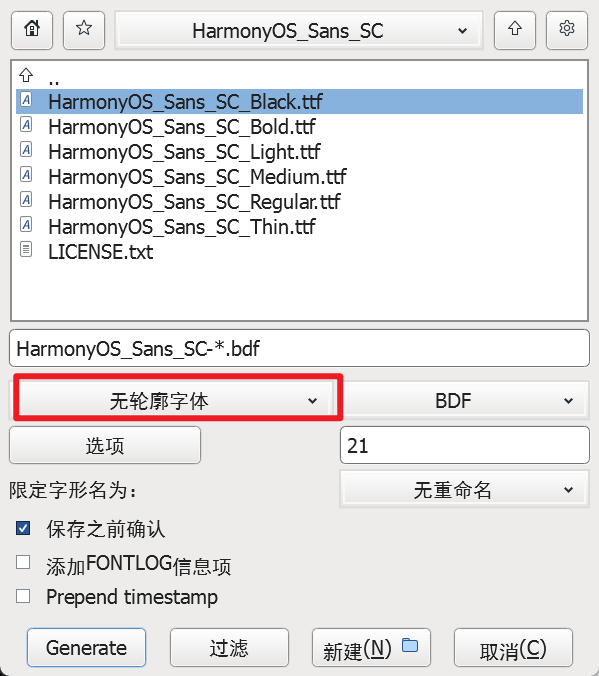
元素-字体信息-通用,去掉勾选有垂直尺寸元素-可用位图部件,75dpi屏幕上点的大小输入20,确定元素-再生位图字形,直接点确定即可文件-生成字体,无轮廓字体,Generate
import time
import board
import displayio
from adafruit_display_text import label
from adafruit_bitmap_font import bitmap_font

display = board.DISPLAY

font_cn_file = "fonts/HarmonyOS_Sans_SC-21.bdf"
font_cn = bitmap_font.load_font(font_cn_file)

text_group = displayio.Group(
    scale=1,
    x=0,
    y=0,
)

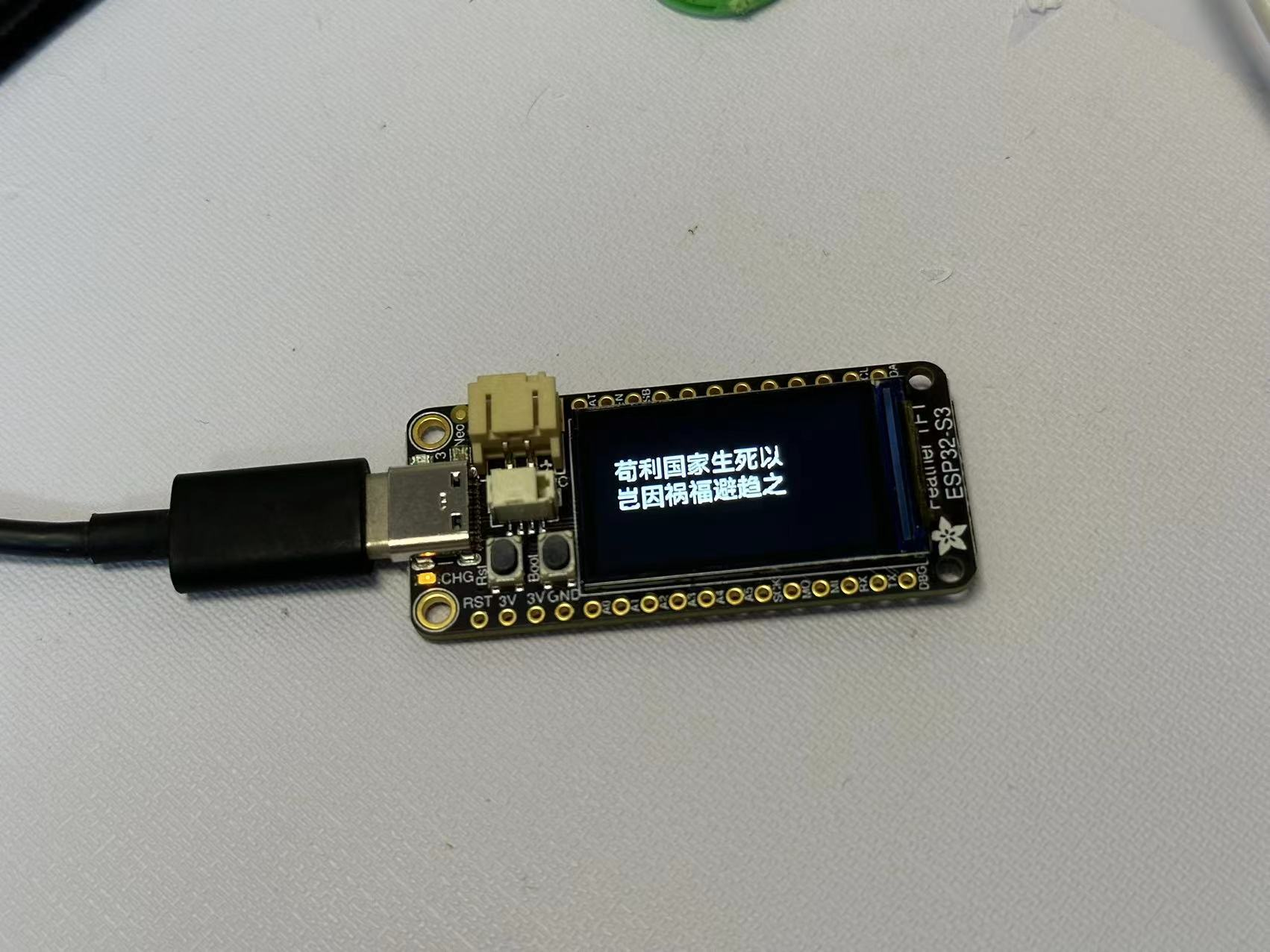
text_cn = "苟利国家生死以\n岂因祸福避趋之"
text_cn_area = label.Label(font_cn, text=text_cn, color=0xFFFFFF, x=20, y=50)
text_group.append(text_cn_area)

display.show(text_group)
while True:
    pass
参考资料:
- https://learn.adafruit.com/custom-fonts-for-pyportal-circuitpython-display
- https://home.gamer.com.tw/creationDetail.php?sn=4117676
# 任务 2:网络功能使用(必做任务)
任务要求:完成网络功能的使用,能够创建热点和连接到 WiFi
搭配器件:Adafruit ESP32-S3 TFT Feather
任务说明:这个任务同样可分为两点,一是连接到 WIFI,二是创建热点。
连接到 WIFI
跟着官方教程就可以完成。
在 settings.toml 添加
CIRCUITPY_WIFI_SSID  = "WIFI SSID"
CIRCUITPY_WIFI_PASSWORD = "WIFI密码"
code.py
import os
import ssl

import adafruit_requests  # 需要安装扩展
import socketpool
import wifi

TEXT_URL = "http://wifitest.adafruit.com/testwifi/index.html"

# 连接WiFi
wifi.radio.connect(os.getenv("CIRCUITPY_WIFI_SSID"), os.getenv("CIRCUITPY_WIFI_PASSWORD"))

print("开发板已连接到WiFi")
print("开发板IP地址", wifi.radio.ipv4_address)

pool = socketpool.SocketPool(wifi.radio)
requests = adafruit_requests.Session(pool, ssl.create_default_context())

print("网络请求网址", TEXT_URL)
response = requests.get(TEXT_URL)
print("请求返回内容")
print("-" * 40)
print(response.text)
print("-" * 40)

while True:
    pass
创建热点
设置热点就更加简单了,只需要一个函数就可以。
import wifi

# 设置热点的SSID和密码
wifi.radio.start_ap("ESP32", "12345678")
print("MAC:", "{:02x}:{:02x}:{:02x}:{:02x}:{:02x}:{:02x}".format(*wifi.radio.mac_address))
while True:
    pass
参考资料:
- https://docs.circuitpython.org/en/latest/shared-bindings/wifi/index.html
# 任务 3:控制 WS2812B(必做任务)
任务要求:使用按键控制板载 Neopixel LED 的显示和颜色切换
搭配器件:Adafruit ESP32-S3 TFT Feather
功能说明:这个任务只要把官方视频的按键 + 炫彩灯珠结合一下就可以完成。
import random

import board
import digitalio
import neopixel  # 需要安装扩展

# WS2812B 电源控制
power = digitalio.DigitalInOut(board.NEOPIXEL_POWER)
power.direction = digitalio.Direction.OUTPUT
power.value = True

# WS2812B设置
pixel = neopixel.NeoPixel(board.NEOPIXEL, 1)
# 亮度
pixel.brightness = 0.1


# 按键对象
# board.BUTTON 与 board.BOOT0 等同
button = digitalio.DigitalInOut(board.BUTTON)
# 设置为输入,上拉,即button.value默认为不按-高-True,按下-低-False
button.switch_to_input(pull=digitalio.Pull.UP)


# 按键是否按下
isDown = False
while True:
    buttonIsDown = not button.value
    if buttonIsDown and not isDown:
        # 按下 且为 第一次检测到按下
        isDown = True
        # 随机颜色
        pixel.fill((random.randint(0, 255), random.randint(0, 255),random.randint(0, 255)))
    elif not buttonIsDown and isDown:
        # 松开 且为 第一次检测到松开
        isDown = False
# 分任务 3:数据检测与记录
按一定时间间隔连续记录温度 / 亮度信息,保存到 SD 卡,并可以通过按键调用查看之前的信息,并在屏幕上绘图
搭配器件:
- Adafruit ESP32-S3 TFT Feather
- Adafruit LTR-329(光线传感器)
- Adafruit MCP9808(温度传感器)
- CH376S(Micro SD 卡模块)
在本次实验中,需要用到 3 个模块,其中两个传感器使用 I2C 通信,SD 卡模块使用 SPI 通信,因此需要对着两种通信方式有所了解,并且了解 ESP32 开发板对应的引脚(参考 1)
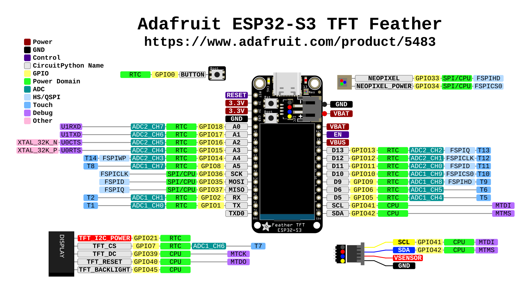
接线
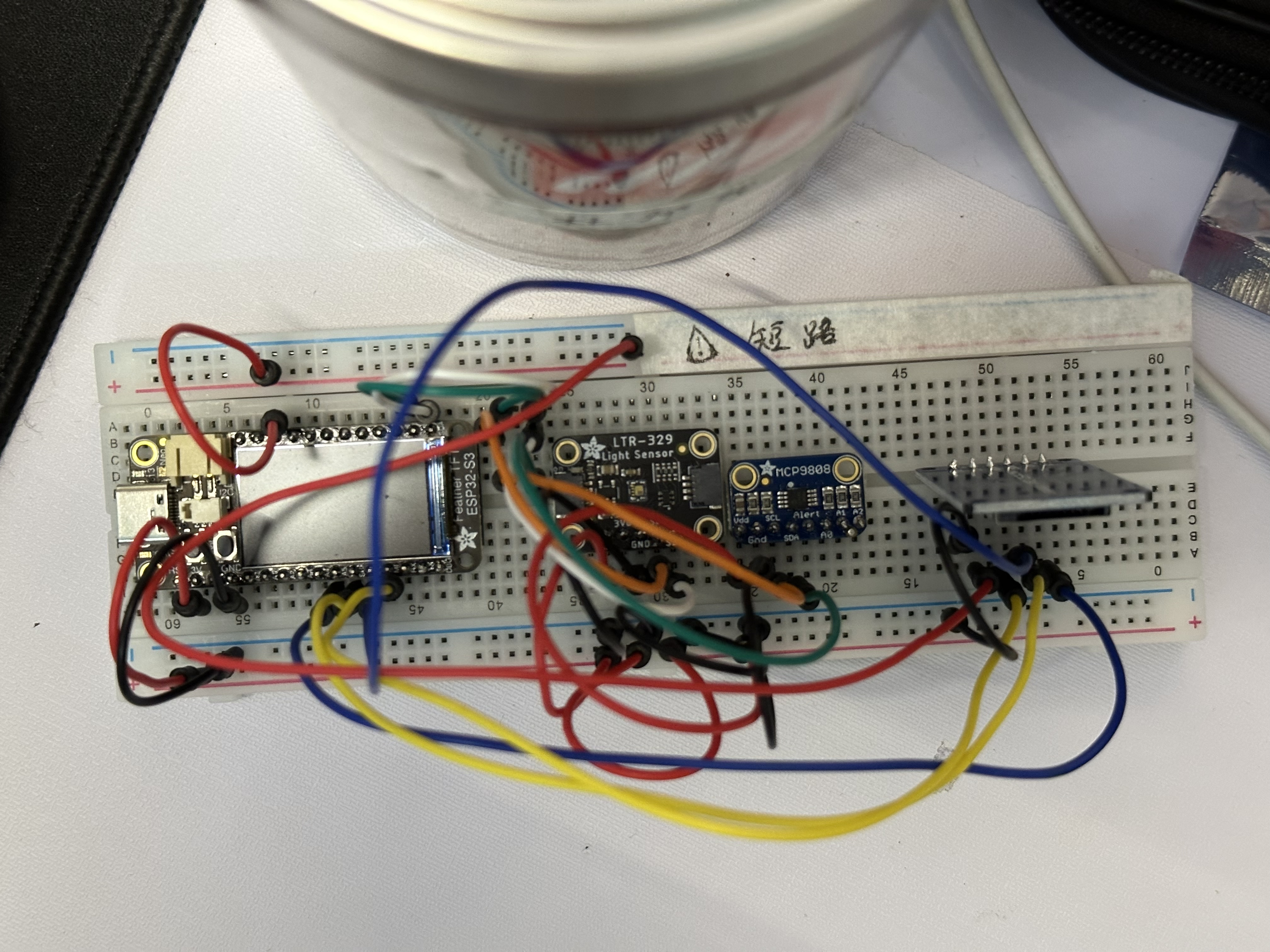
- LTR-329(光线传感器)- I2C
- VIN:接 3.3V
- GND:接地
- SCL:接 SCL
- SDA:接 SDA
- MCP9808(温度传感器)- I2C
- Vdd:接 3.3V
- Gnd:接地
- SCL:接 SCL
- SDA:接 SDA
- CH376S(Micro SD 卡模块)- SPI
- GND:接地
- VCC:接 5V(VUSB 引脚)
- MISO:接 MISO
- MOSI:接 MOSI
- SCK:接 SCK
- CS:A5(或任意 GPIO 接引)
笔记
在 USB 供电下,实测 VBAT 引脚电压 4V,VUSB 引脚电压 5V
参考代码
import asyncio
import os
import wifi
import socketpool
import adafruit_ntp
import rtc
import digitalio
import adafruit_sdcard
import storage
# 显示屏
import displayio
import terminalio
from adafruit_display_text import label

# 处理记录
async def hanlderRecord(ltr329, mcp,sdcard):
    # 挂载SD卡
    print("VfsFat")
    vfs = storage.VfsFat(sdcard)
    print("mount")
    storage.mount(vfs, "/sd")
    print("mount ok")

    # 清空文件
    # fo = open(filePath, "w")
    # fo.write("")
    # fo.close()

    while True:
        # 时间戳,可见光+红外光,可见光
        t = time.time()
        text = str(t) + ","

        # 光线传感器
        # 可见光+红外光
        text += str(ltr329.visible_plus_ir_light) + ","
        # 可见光
        text += str(ltr329.ir_light)+ ","

        # 温度传感器
        text += str(mcp.temperature)

        # 写入SD卡,追加模式
        fo = open(filePath, "a")
        fo.write(text + "\r\n")
        fo.close()

        print(text)
        # 每60秒写入一次
        await asyncio.sleep(60)

# 格式化时间戳
def _format_datetime(timestamp):
    tz_offset_seconds = 60 * 60 * 8  # 东八区
    get_timestamp = int(timestamp + tz_offset_seconds)
    current_unix_time = time.localtime(get_timestamp)
    current_struct_time = time.struct_time(current_unix_time)
    return "{:02}-{:02} {:02}:{:02}".format(
        current_struct_time.tm_mon,
        current_struct_time.tm_mday,
        current_struct_time.tm_hour,
        current_struct_time.tm_min,
    )

# 打印记录
def printRecord(text_area,pageNum,pageSize):
    headerText = "Time  Visible+IR   IR   Temperature\r\n"
    with open(filePath, 'r') as file:
        lines = file.readlines()
        pageTotal = len(lines)
        maxPageNum = (pageTotal + pageSize - 1) // pageSize

        if pageNum < 1 or pageNum > maxPageNum:
            pageNum = 1

        start_index = (pageNum - 1) * pageSize
        end_index = start_index + pageSize
        page_lines = lines[start_index:end_index]

        text = ""
        # 生成文本
        for line in page_lines:
            # ,分割
            line = line.split(",")

            # 时间
            current_date = "{}".format(_format_datetime(int(line[0])))
            text += current_date+"\t"

            # 可见光+红外光
            text += line[1]+"\t"+line[2]+"\t"

            # 温度 精确到小数点后1位
            text += "{:.1f}".format(float(line[3]))+" C"

            text += "\r\n"

    floorText = "Page " + str(pageNum) + "/" + str(maxPageNum)
    text_area.text = headerText + text + floorText

# 处理屏幕输出
async def hanlderScreen(button):
    display = board.DISPLAY
    text_group = displayio.Group( scale=1, x=0, y=0 )
    text_area = label.Label(terminalio.FONT, text="", color=0x000000, x=0, y=5,background_color=0xFFFFFF)
    text_group.append(text_area)  # Subgroup for text scaling
    display.show(text_group)

    # 分页信息
    pageTotal = 0 # 总数据数
    pageNum = 1 # 当前页
    pageSize = 7 # 每页数据数

    printRecord(text_area,pageNum,pageSize)
    isDown = False
    while True:
        buttonIsDown = not button.value
        if buttonIsDown and not isDown:
            # 按下 且为 第一次检测到按下
            isDown = True
            print("Button down")
        elif not buttonIsDown and isDown:
            # 松开 且为 第一次检测到松开
            isDown = False
            pageNum+=1
            printRecord(text_area,pageNum,pageSize)
        await asyncio.sleep(0.1)


async def main(ltr329, mcp, sdcard,button):
    # 连接WiFi
    wifi.radio.connect(os.getenv("CIRCUITPY_WIFI_SSID"), os.getenv("CIRCUITPY_WIFI_PASSWORD"))
    print("开发板已连接到WiFi")
    print("开发板IP地址", wifi.radio.ipv4_address)
    pool = socketpool.SocketPool(wifi.radio)

    time.sleep(1)
    # 使用ntp时间更新系统时间
    ntp = adafruit_ntp.NTP(pool, server="time1.cloud.tencent.com")
    rtc.RTC().datetime = ntp.datetime

    asyncio.create_task(hanlderRecord(ltr329, mcp,sdcard))
    asyncio.create_task(hanlderScreen(button))
    while True:
        await asyncio.sleep(1)

import time
import board
from adafruit_ltr329_ltr303 import LTR329
import adafruit_mcp9808

# 光线传感器
i2c = board.I2C()  # uses board.SCL and board.SDA
time.sleep(0.1)  # sensor takes 100ms to 'boot' on power up
ltr329 = LTR329(i2c)

# 温度传感器
mcp = adafruit_mcp9808.MCP9808(i2c)

# 读卡器
spi = board.SPI()
cs = digitalio.DigitalInOut(board.A5)
sdcard = adafruit_sdcard.SDCard(spi, cs)
filePath = "/sd/record.csv"

# 按键对象
# board.BUTTON 与 board.BOOT0 等同
button = digitalio.DigitalInOut(board.BUTTON)
# 设置为输入,上拉,即button.value默认为不按-高-True,按下-低-False
button.switch_to_input(pull=digitalio.Pull.UP)

asyncio.run(main(ltr329, mcp, sdcard,button))
参考资料:
- Pinouts | Adafruit ESP32-S3 TFT Feather | Adafruit Learning System (opens new window)
- Overview | Adafruit LTR-329 and LTR-303 Light Sensors | Adafruit Learning System (opens new window)
- Overview | Adafruit MCP9808 Precision I2C Temperature Sensor Guide | Adafruit Learning System (opens new window)
